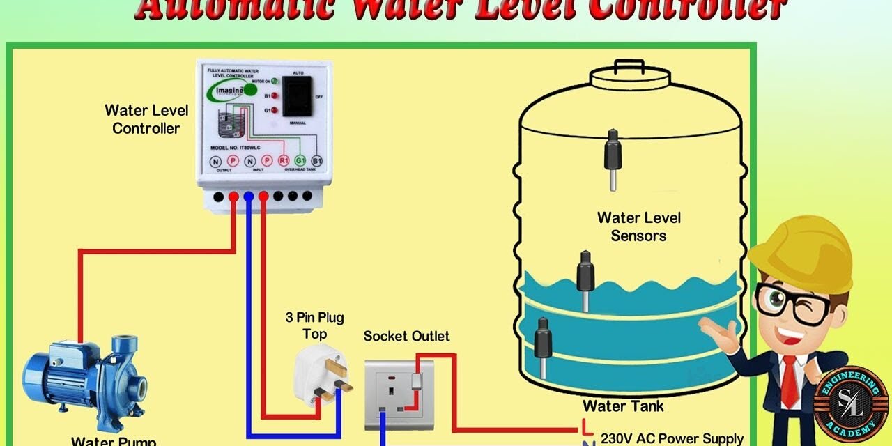
Calibrating electronic liquid level controllers for different tank sizes and liquid types is essential to ensure accurate and reliable performance. This process involves adjusting the controller settings and sensors to suit the specific requirements of the tank or system, taking into account factors like the size of the tank, the characteristics of the liquid, and the application requirements. Below are the steps and considerations involved in calibrating these controllers:
1. Selecting the Appropriate Sensor
- Sensor Type: Depending on the application and liquid type, different types of sensors (e.g., capacitive, ultrasonic, conductive, or float-based) are selected. Each sensor type works best with specific liquid properties and tank configurations.
- Capacitive sensors are used for non-metallic tanks and when measuring liquid levels in water, oils, or other non-corrosive liquids.
- Ultrasonic sensors work well for non-contact measurement of liquid levels in various liquids, including viscous or non-conductive liquids.
- Conductive sensors are suitable for conductive liquids such as water with dissolved salts.
- Float-based sensors are common in simple applications and are mechanically based, where a float rises and falls with the liquid level.
2. Tank Size and Geometry Consideration
- Tank Dimensions: The calibration must account for the size and shape of the tank. For example, if the tank is conical or cylindrical, the liquid volume may not be a linear function of the height of the liquid, and the controller needs to be programmed to account for this non-linearity.
- Level Measurement: Some systems allow for adjustments in the measuring range. For instance, if a sensor is measuring liquid levels from 0 to 10 meters, the controller must be set up to respond appropriately to this range.
3. Liquid Properties
- Density and Viscosity: Different liquids (e.g., water, oil, chemicals) have varying densities and viscosities. These properties can affect the sensor’s accuracy. Calibration may involve adjusting settings to compensate for these differences. For example, a denser liquid like oil may require different compensation than a less dense liquid like water.
- Conductivity: For conductive sensors, the electrical conductivity of the liquid can impact performance. Calibration may involve adjusting the sensitivity or threshold for detecting the liquid level.
- Foam or Bubbles: In some processes, liquids may foam, creating false readings. The controller might need to be calibrated to filter out foam and only detect the true liquid level.
4. Sensor Placement
- Mounting Position: The placement of the sensor within the tank must be carefully chosen to avoid interference and ensure accurate readings. For example, sensors should be positioned away from tank walls, agitators, or turbulence that could distort measurements.
- Dead Zones: Certain areas within tanks (e.g., near the bottom or top) might not provide accurate readings due to physical obstructions or liquid flow patterns. These zones must be accounted for during calibration.
5. Setting the Measurement Range
- Minimum and Maximum Levels: The calibration process defines the minimum and maximum liquid levels in the tank. For instance, if a tank has a capacity of 1000 liters, the controller is calibrated to recognize and respond when the liquid is at levels corresponding to 0% (empty) and 100% (full).
- Hysteresis and Deadband: Calibration also involves setting a deadband (a small range of variation within which the system does not respond). This avoids constant switching due to small fluctuations in the liquid level, ensuring stable operation.
6. Signal and Output Calibration
- Signal Adjustment: The signal output from the sensor (e.g., voltage, current, or digital signal) is calibrated to correspond with specific liquid levels in the tank. For instance, a 4-20 mA signal might be used to represent 0% to 100% liquid levels.
- Zero and Span Adjustment: Zero calibration involves setting the signal to represent an empty tank, while span calibration defines the signal at full capacity. Adjusting both ensures the controller responds appropriately to liquid levels across the entire measurement range.
7. Compensation for Environmental Factors
- Temperature Compensation: In many cases, temperature can affect the properties of the liquid (e.g., expansion or contraction). Some controllers offer temperature compensation settings that allow the system to adjust readings based on the measured temperature of the liquid.
- Pressure Compensation: If the liquid pressure is significantly different from normal, it might also be necessary to calibrate the system to account for pressure variations, especially in closed systems.
8. Testing and Fine-Tuning
- Test Run: After initial calibration, a test run should be performed to verify the accuracy of the liquid level readings. During testing, the controller is monitored, and adjustments are made as necessary to fine-tune the sensor’s response to the tank and liquid conditions.
- Re-calibration: Depending on the application and how the tank is used, recalibration may be necessary periodically, especially if the liquid type or tank size changes.
9. Integration with the Control System
- Integration: The calibrated controller is integrated into the plant’s control system or SCADA system for continuous monitoring and control. It may communicate with other controllers to trigger alarms or control pumps and valves based on the liquid level.
- Data Logging: Many modern systems allow for logging of liquid level data, which can be useful for long-term monitoring and predictive maintenance.
10. User Interface and Calibration Adjustment
- User-Friendly Calibration Tools: Many advanced electronic liquid level controllers come with user-friendly interfaces that allow operators to easily adjust and calibrate the system using digital displays, touchscreens, or software.
- Field Calibration: For some systems, field calibration can be performed without the need to remove or relocate sensors, providing flexibility for on-site adjustments.
Conclusion
Calibration of electronic liquid level controllers ensures accurate and reliable operation for different tank sizes, liquid types, and process conditions. By considering factors such as tank geometry, liquid properties, and environmental factors, manufacturers can tailor the controllers to suit their specific needs. Regular calibration and maintenance of these systems are crucial for optimal performance and avoiding issues such as inaccurate readings, system malfunctions, or inefficiencies.
Hashtags
#TankSizeCalibration #CustomTankLevelControl #AdjustableTankSizeCalibration #TankSpecificLevelControl #LiquidLevelControlForTanks #FlexibleTankLevelCalibration #SizedLevelControllers #TankSizeSpecificLevelSensors #OptimizedTankCalibration #TankCustomizedLevelMonitoring #LiquidTypeCalibration #CustomLiquidLevelControl #LiquidSpecificLevelSensors #FluidTypeLevelMonitoring #ViscosityBasedLevelControl #LiquidCompatibilityCalibration #LiquidSpecificElectronicSensors #AdaptedForLiquidTypeControl #CalibratingForDifferentLiquids #TailoredLiquidLevelMeasurement #VersatileLevelControllers


